mrb's blog

DIY Coin-sized SATA Power Module to Replace a Harddrive Docking Station

Keywords: hack hardware sata

I find harddrive docking stations too bulky, slow, and unreliable. They are (1) inconvenient to carry when travelling light with a laptop, (2) offer relatively little throughput because the USB ones are limited to 480Mbps and the eSATA ones are often internally bottlenecked to 1.5Gbps due to the bridge chips they use (nevermind that none support SATA 6Gbps), and (3) are not reliable/act in strange ways when a drive is failing, which is sometimes the reason I put the drive in a docking station —to investigate it— and I wonder if it is the station or the drive that is failing.

Therefore I felt compelled to design and build a coin-sized SATA power module able to power a drive while the latter can be directly connected to a computer via a plain SATA or eSATA cable. I have used it for a couple of days and am very happy with it. Compared to a docking station, my solution is smaller, cheaper, faster, more reliable, and allows connecting any SATA peripherals (optical disc drives, SATA port multipliers):

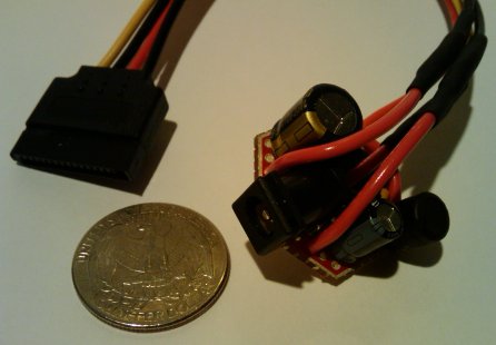
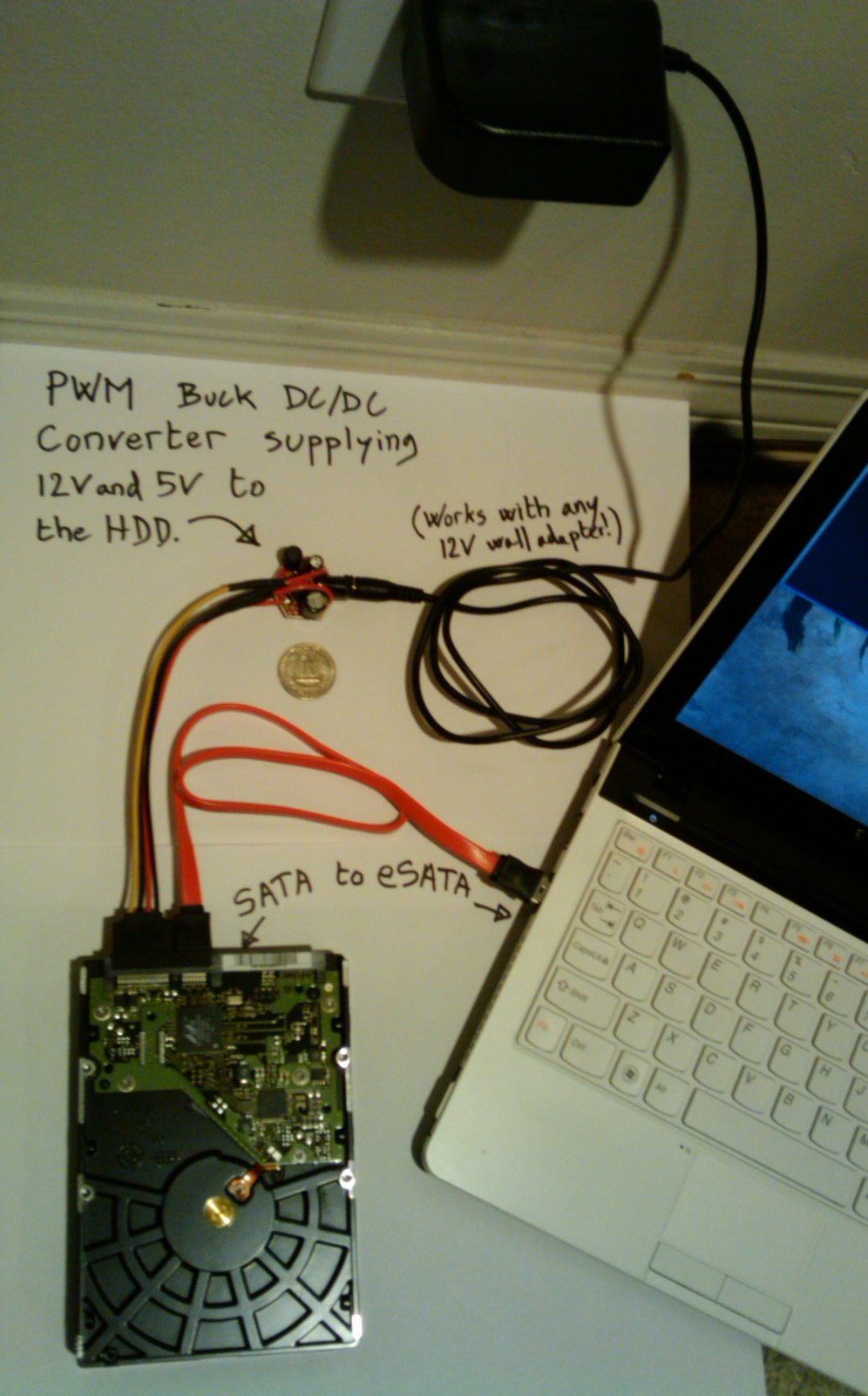
Total cost and time involved were about 9 USD and one afternoon. The power module is compatible with any 12V wall adapter, as long as its current rating is sufficient for the drive —personally I use the 2A-rated adapter from the docking station it replaced :-) It steps down 12V to 5V, and supplies both voltages to the drive:

Design

Before I started this project, I knew that a SATA power cable theoretically supplies 3 voltages: 3.3V, 5V, and 12V, but that no drive on the market uses/needs 3.3V. I started by disassembling my Rosewill RX-DUS100 docking station to reverse-engineer the design and find how it was supplying 12V and 5V to the drive. 12V came directly from the output of the wall adapter whereas 5V came from the output of a chip labelled Techcode TD1509 which I quickly found out was, with 2 capacitors, a diode, and an inductor nearby, forming a circuit called a PWM buck DC/DC converter.

I must ashamedly admit I had never heard of buck converters before (hey, electronics is a hobby I rarely practice!) Now armed with the key piece of information I needed, I decided my plan will be to re-use the 12V wall adapter from the docking station, and to build a buck converter on a PCB as small as possible with a DC power jack as the input and a SATA power cable as the output.

I measured the current draw at 12V and 5V on a handful of harddrives and cross-checked with the HDD vendors' datasheets. Drives are never rated more than about 2.5A @ 12V and 0.7A @ 5V. In practice my measurements showed no more than 1.5A @ 12V and 0.6A @ 5V. Power consumption on the 5V rail is pretty much constant, whereas 12V spikes to ~1.5A during spin-up then falls back to ~0.5A. As to my docking station, its 12V wall adapter is rated 2A, and its Techcode TD1509 converter is rated 2A @ 5V (overspec'd because it powers a few other chips in addition to the drive.) With these number in mind, I decided to design my converter for minimum 1A @ 5V.

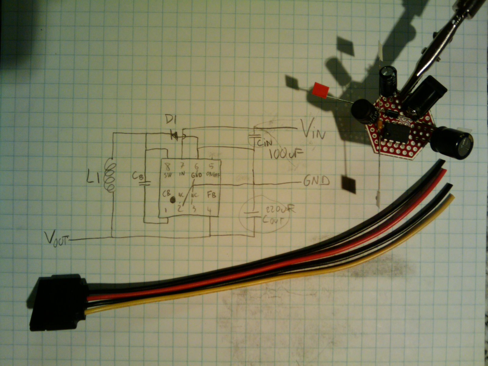
I searched around on Octopart, Digikey, and found many 5V buck converters. I reduced my search criteria to the high-efficiency, through-hole ones requiring few external components that were inexpensive. I settled on the Nat Semi LM2675, a 1A, DIP8 package, DC/DC converter to 5V. I implemented the reference circuit from the datasheet, and selected external components to match my design specifications (12V input, 1A @ 5V output.) Full bill of materials:

I found a layout that works well with this PCB, while minimizing the length of certain traces (eg. the Schottky diode needs to be as close to the LM2675 as possible):

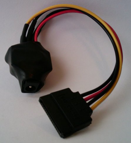
Finally I put some heat-shrink tubing to finish the product:

Possible Improvement

The current design requires a 12V wall adapter because this 12V input is output directly to the drive. One could add another DC/DC conversion step (at the cost of increased board size) to regulate 12V, thereby making the SATA power module compatible with a wider range of input voltages, such as a laptop power adapter. One less adapter to travel with!

I would be very happy to see a commercial product like mine. I found only one on Newegg but it is still too bulky and clumsy to my taste (separate thick IEC power cord, brick adapter, 4-pin molex power cable, 4-pin molex to SATA power adapter).

Comments

sr wrote: Great article! Thanks!

Could you give more details on:

- "bridge chips" bottlenecks? (maybe another article on the docking station dissasembly?)
1.5Gbps is a bottleneck for SSDs, right? not spinning harddrives, yet?

- laptop having esata port (never saw one before, what's on the picture?)
14 Mar 2011 05:17 UTC

mrb wrote: Bridge chips provide USB or SATA uplinks to a host (computer) and a SATA downlink to a device (drive). It is the most important chip in a docking station. It is very easy to identify when opening up a dock station, it is the biggest chip (BGA package). A common supplier of such chips is JMicron:

http://www.jmicron.com/Product_list.htm

For example my docking station uses the JMicron JMB20336. It is in theory capable of SATA 3Gbps according to the bridge chip datasheet, but I see it negotiate speeds of only 1.5Gbps with my laptop which supports 3G. On Linux, the SATA speed negotiated by a device is usually listed in the kernel messages (dmesg). JMicron has more detailled datasheets (but they are not available to the public), and I presume they state it supports 3G on the downlink, but not on the uplink. Of course the docking station is branded as "supporting 3Gbps". Sigh :-/ Or perhaps the bridge chip downgrades to 1.5Gbps due to EMI issues, poor traces, who knows? That's part of why I ditched my docking station, and others, after all.

So I built my module and, ta-da, all the drives and laptops I have now work at 3G with a passive SATA cable.

You are correct that 1.5Gbps is usually not a bottleneck with a single 7200 RPM HDD. However it is one when reading from the drive cache (which can mostly only be shown in synthetic benchmarks), as well as recent 15k RPM HDDs, SSDs, and also SATA port multipliers.

As to my laptop (Lenovo U160), yes it has an eSATA port. It was one of my requirements when I purchased it. The story of the amount of time I spent researching a laptop that met my needs is worthy of another blog post :-)
14 Mar 2011 08:03 UTC

sr wrote: Merci encore pour les infos.

- I use this one http://www.ldlc.com/fiche/PB00080893.html
Will try to get the chip info. Needs also to test if esata hotplug has progressed.

- "from the drive cache": ah yes, forgot this one.

- "amount of time I spent researching a laptop that met my needs is worthy of another blog post " : yes, lots of laptops that are the same, but few features.
Other example: it seems impossible to find resolutions that were available few years ago (1440x900 12" or 1600x1200 14/15"). Even the X series does not seem to have an esata port!
14 Mar 2011 08:50 UTC

Alex wrote: A possible redesign you could go for a longer rather than wider approach. Try and fit as much of it as possible in the same height and width of the power connector. Making it look like just long plug. 14 Mar 2011 17:25 UTC

Roger wrote: Parts from those supply houses get expensive when purchased one at a time and all the postage is added. Have you thought about putting together DIY kits and selling them for, say, 20% above cost? Many of us know how to solder or have a friend who does, we just don't have the patience to round up the individual parts.

If you did this, a short Youtube video would be good advertising.
23 Mar 2011 21:05 UTC

mrb wrote: Sorry I can't sell kits.

However I hope you noticed I provided direct links to the exact Digikey or Sparkfun parts for this project, so there is no "hunting" necessary to find them.
25 Mar 2011 06:15 UTC

ACG wrote: If there is anyone out there that has read this page top to bottom, I am interested in obtaining a few 'kits'. Call it a first-timers' worry-free order; perhaps I'll successfully create one on the first try, though I would like to have a 'testable' adapter before creating very many. I see this as a business opportunity for someone, though have too much on my plate right now to even think of creating a quantity order for adaptation/sale. 17 Apr 2011 03:35 UTC

ACG wrote: address.unknown@myfairpoint.net is a legitimate eddress. 17 Apr 2011 03:36 UTC

Portable Hard Drive Deals wrote: Looks difficult, will do it anyway! 23 Sep 2011 06:20 UTC

Dude wrote: I need something like this, many thanks for the links to the parts mrb. Does your sata to esata cable have the required extra shielding of an external interconnect? Perhaps you are not too concerned if it is just for testing purposes.

From the External Serial ATA White Paper.

Additional steps were taken to modify the cable by adding an extra layer of shielding surrounding both of the differential signal pairs in the cable. In a standard internal cable, each pair is shielded individually. This shielding remains in the external cable, but an additional over wrap is also provided.
16 Oct 2011 23:56 UTC

mrb wrote: The SATA to eSATA cable in the picture does not seem to have this extra shielding. But I have a few other cables that have it.

The SATA protocol has built-in error correction anyway, but I would say if you have the choice, be conservative and go with an extra-shielded cable to reduce the theoretical error rate.
17 Oct 2011 01:43 UTC

Dude wrote: Thanks for the info. Are you able to put up a picture of the reverse side of the hex board after the parts are mounted. That way I can follow the physical traces. I am pretty newb to reading electrical schematics (even simple ones). 17 Oct 2011 10:08 UTC

mrb wrote: I am sorry. I already put heat-shrink tubing. I would have to cut it open... 18 Oct 2011 03:51 UTC

Lucas Anthony@laptop overheating problem wrote: please be more specific. i want to apply this on my laptop. this idea of your is interesting. 26 Oct 2011 02:43 UTC

Ryan Gibson wrote: Hey,

Great build you've put together here. Do you have an email I can grab you on? I have a few questions i'd love to send your way.

Thanks

Ryan
02 Feb 2012 10:06 UTC

mrb wrote: My email address is listed on my personal page: www.zorinaq.com 03 Feb 2012 03:25 UTC

Joerg wrote: Good stuff, thank you! I would like to build a NAS using the marsboard. I am thinking of building a similar rig to power a 3.5" drive. It would be great if I could also throw in a USB supply to also power the marsboard itself from the same plug.
Would it be possible to run the marsboard in parallel to the SATA 5V line, or would that need to be decoupled - and how?
27 Nov 2013 12:41 UTC

mrb wrote: Yes the 5V output of my module can be fed into both SATA and USB in parallel. 29 Nov 2013 08:56 UTC

Gyuri wrote: Hello Marc,

Thanks for this great post!

I'd like to make a similar power "converter" with this module: http://www.ebay.com/itm/371348168950

The description says that the load capacity max is 3A, typical is 1.5A. You wrote that your measurements were 0.6 and 0.7A @ 5V

What's your opinion about this little module? Should I use capacitor on the output or heatsink on its chip?
08 Mar 2016 18:43 UTC

mrb wrote: Gyuri, yes you probably will need to add a bypass capacitor on the output, but other than that the module should work fine. No heat sink necessary (it's 92% efficient, so at 1A @ 5V it would dissipate only 0.4W in heat). 14 Mar 2016 02:48 UTC

Gyuri wrote: Yesterday the module arrived so I made my sata power converter. I add a capacitor as you suggested. Writing with the 3.5" HDD now for 30 minutes, and it's ok & the module is not hot. :D

Thanks for your help!

Gyuri
01 Apr 2016 18:33 UTC

NetScalerTrainer wrote: @Gyuri could you post your final design?
What bypass capacitor did you use?
Could you make me one of these?

@Marc I think my drive is not getting power, I want to power it externally with one of these to double check. I have a MOLEX 4-pin to SATA power cable but that would require firing up another PC just to provide power and I have little space.

You can also find me on youtube NetscalerTrainer channel, or twitter @NetscalerTrain
Really appreciate the help!
07 Feb 2017 20:55 UTC

mrb wrote: NetScalerTrainer: a 220uF aluminum capacitor is just fine as an output cap. I hope your issue is fixed by now. If not I would suggest using a multimeter to verify if it is getting power. Pierce the insulation of the wires with piercing probe (or a needle). 11 Mar 2017 22:44 UTC

Gould wrote: Hello.
Awesome build! Could you please upload a schematic and if possible, show where all the wires go? I'm a noob at this and would love some help.
Thank you.
27 Jan 2018 20:17 UTC