After putting about 100 hours of full load on my 4 x AMD Radeon HD 5970 brute forcing machine, I completely disassembled it to visually inspect all internal power connectors, cables, the graphics cards, motherboard, and the PSUs. I decided to redesign how power is distributed to the PCIe slots. I explain why and how below.
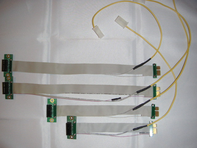
Each HD 5970 draws 3.7A@12V from the slot alone, excluding the 6-pin and 8-pin power connectors. The four slots are powered by the 24-pin ATX connector. That means 14.8A@12V total, or 7.4A through each of the two 12V wires in this connector, which is actually over the official ATX spec (6A/wire). When I designed the machine, I willingly ignored this fact and went over spec, if only to stress-test the system and to validate whether it was a fair or under-estimated limit. During the test, I noticed that the plastic around the two 12V wires in the connector was hot, which I expected. Because the quality of the contact between the metallic terminals in these connectors is not perfect, and because the wires are crimped instead of soldered, there is a small resistance. The higher the current, the higher the heat dissipation. After about 100 hours, the plastic started developping a slight yellowish color. Knowing that this spec was therefore fair and realistic (unlike the PCIe power connectors which are grossly overspec'd for what they carry), I made a simple change to the power distribution to the 4 x HD 5970. I modified each of the four flexible PCIe extenders to re-route the five 12V lines (PCIe pins A2, A3, B1, B2, B3) to a single 16AWG stranded wire directly connected to one of the 12V outputs of the power supply. [Update 2011-06-19: Pin B3 is defined as "reserved" in the PCIe specs I have access to. But my PCIe extenders have B3 wired to the other 12V lines, so I presume that more recent versions of the PCIe spec re-assigned B3 to carry the 12V voltage.]
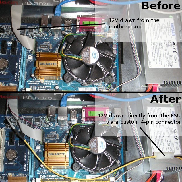
The graphics cards now draw 12V directly from the PSU. The current on the 12V lines on the 24-pin connector dropped from 14.8A to 0.1A. The picture shows how the new power distribution looks like for one HD 5970 card.
It took me less than 15min to modify my four extenders: cut ribbon cable, solder wire, cover with electrical tape, put heat-shrink tubing on, crimp a Molex terminal on the other end, and slide into a 4-pin Molex housing. I wish someone would mass-manufacture this type of extender. This is a universal accessory for using as many high-powered graphics cards as possible with any motherboard.